
Features
Advanced internal feedback circuit ensures excellent linearity, stable voltage performance, and strong resistance to high voltage, high current, and high temperatures.
Fully isolated weak and strong current circuits provide enhanced safety and reliable control performance.
Suitable for a wide range of automated control applications, including chemical processing, food machinery, packaging equipment, textile machinery, CNC machine tools, entertainment equipment, and other industrial automation systems.
Specifications
| Model | SCR-3 380V | |||
| Module Type | Three-phase | |||
| Load Current (Optional) | 10A,25A,40A,60A,80A,100A,120A,150A,200A | |||
| Load Voltage | 380±15%VAC | |||
| Ambient Temperature | -20ºC~+75ºC | |||
| Control Mode (Optional) | 0-5VDC, 0-10VDC,4-20mA,10K | |||
| On Voltage | ≤2V | |||
| Off Leakage Current | ≤10mA | |||
| On-off Time | ≤10mS | |||
| Dielectric Strength | 2000VAC | |||
| Certification | CE | |||
| Insulation Resistance | 500MΩ/500VDC | |||
| Mounting Method | Bolted | |||
| Work Instruction | LED | |||


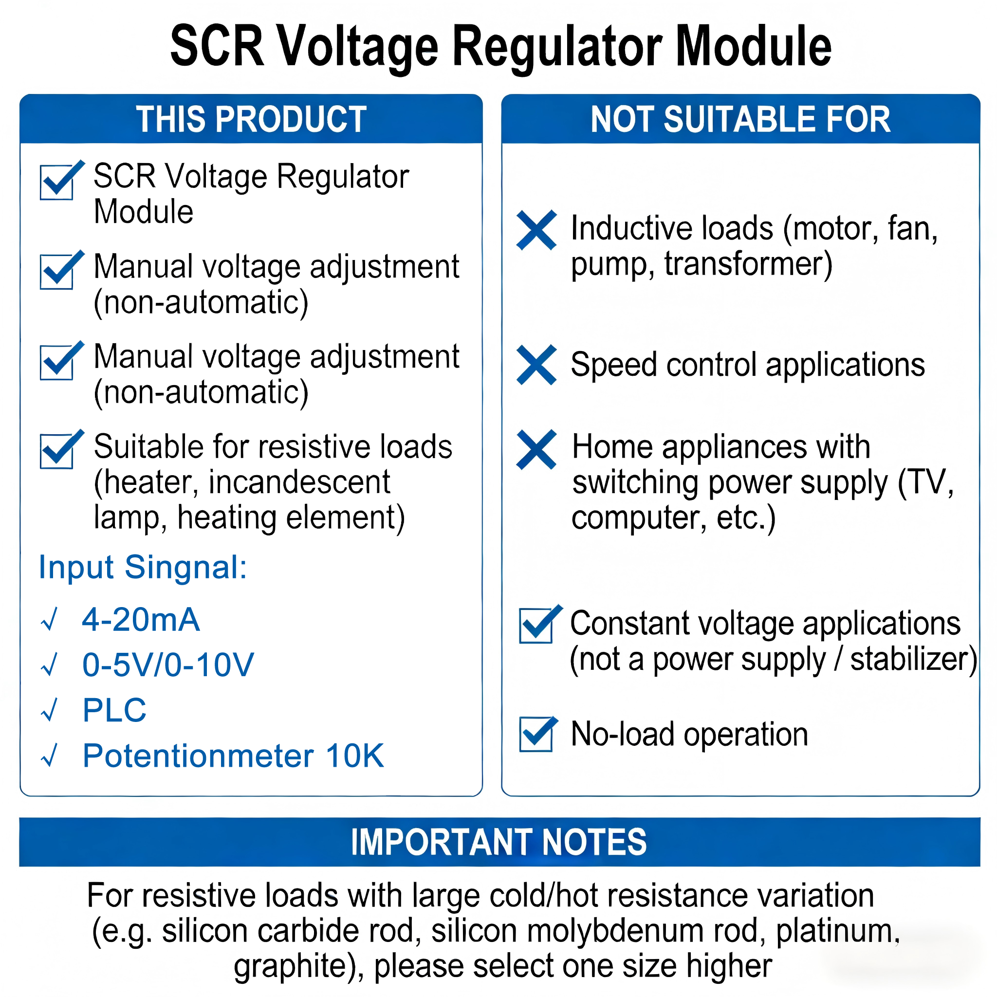
Is This the Right Module for Your Application?
Control Input Wiring
The SCR-3 supports four control input modes. Only one mode should be active at a time.

|
10k Manual Control input |
Manual Potentiometer ControlThe module provides a built-in 5V supply for use with a 10KΩ potentiometer. |
|
0-5VDC/1-5VDC Control input |
0–5V DC ControlAccepts 0–5V analog signals from a microcontroller. |
|
0-10VDC/2-10VDC Control input |
0–10V DC ControlAccepts 0–10V analog signals from PLCs or other controllers. |
|
4-20mA Control input |
4–20mA ControlAccepts a 4–20mA analog signal from instruments such as temperature controllers. |


Switching Between Control Modes
If both automatic (e.g., 4–20mA) and manual (e.g., 0–5V) control are needed, use a double-throw switch to select between modes.
When multiple signals are connected simultaneously, the stronger signal will dominate.
Installation & Safety Notes
Correct Polarity
All function terminals must remain positive relative to the COM terminal. Reversed polarity may cause uncontrolled output. A higher control voltage results in higher main-circuit output voltage.
Load Current Limits
| Load Type | Maximum Operating Current |
| Resistive loads | ≤60% of rated current |
| Inductive / capacitive | ≤40% of rated current |
| Motor loads | Can not use |
For resistive loads with large cold/hot resistance variation — such as silicon carbide rods, silicon molybdenum rods, platinum, or graphite — select one current rating higher than calculated.
Derating at Low Output Voltage
Operating the module at a small conduction angle (high input, low output) can cause serious overheating. The effective current can exceed the rated value even when the meter reading appears normal.
Keep output voltage above 50% of input voltage where possible.
| Output Voltage | 380V~ | 280V~ | 190V~ | 100V~ | 50V~ |
| Maximum Load Current | 100% | 85% | 60% | 40% | 25% |
Overcurrent Protection
Overcurrent and short circuits are the most common causes of irreversible thyristor failure. Always install fast-acting fuses or air circuit breakers before commissioning.
Heat Dissipation
Install on a properly sized heatsink with thermal interface material. Add forced-air cooling in environments with poor ventilation.
Do Not Operate Under No-Load Conditions
The SCR-3 cannot function without a load connected. After wiring is complete, first connect a small resistive load such as an incandescent lamp to verify normal operation before connecting the actual load.
LED Status Indicators
Green LED — power indicator: confirms the module is receiving power
Red LED — circuit status: steady on or intermittent flashing
indicates normal circuit operation
Product Manual
Download the full SCR-3 product manual for detailed wiring diagrams, selection tables, and technical specifications.
Need Help?
Need help selecting the right SCR module for your application?
Contact us at softstarterpro.com or WhatsApp: +86 18006697926

